Making a Toy Traffic Light
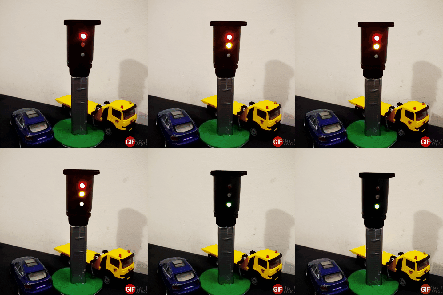
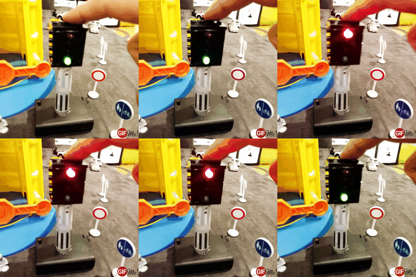
March 9, 2016My son is fascinated by cars with the kind of enthusiasm that only kids are able to bring up. He has a huge collection of toy cars already, so I decided that for his 3rd birthday last year, I would get him something different and built him this toy traffic light.
It is controlled by an Arduino Nano, has three LEDs that feature all the states of Austrian traffic lights and it cycles through these states autonomously. You can find the Arduino code for it on GitHub.
More!
But recently, my son asked me if I could make him another traffic light. This time a pedestrian one. Since these feature just two colors / states (red and green), I figured that an Arduino would really be kind of an overkill for this. Also my son wanted to be able to switch between the traffic light’s states manually, so I figured a toggle button, a Flip-Flop and 2 LEDs would do the trick.
No Code - just Hardware.
I have done a couple of Arduino projects by now but this was the first project that involved no coding and only circuits. This was kind of intimidating at first but also challenging.
Disclaimer: I am a complete and utter noob at electronics.Therefore, if I made mistakes somewhere or you think this build needs improvement, please let me know (in a friendly and respectful way though).
That’s the part list I came up with:
- a red LED
- a greed LED
- 2 x 330Ω protective resistors for the LEDs
- a toggle switch
- a 10kΩ pull-up resistor for the switch
- a 10nF ceramic capacitor to debounce the switch
- a CD4013BE D-Type Flip Flop
- wires
- breadboard
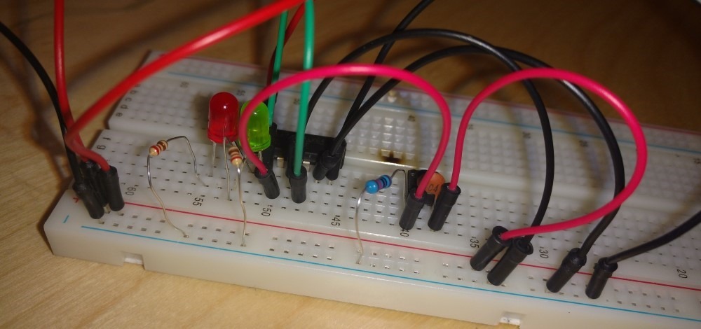
Here’s what the circuit looks like:
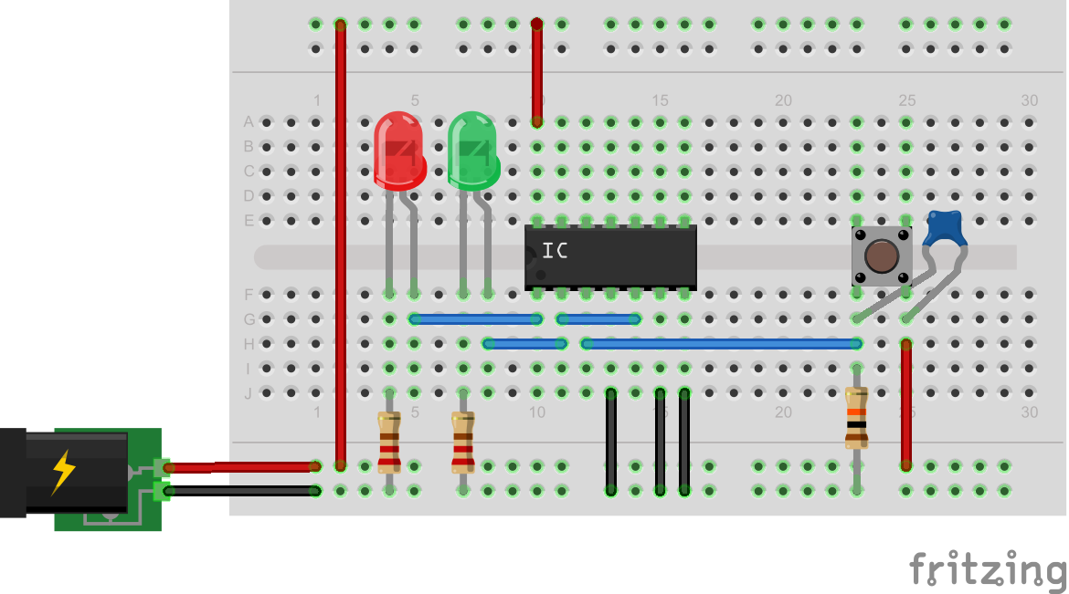
The same circuit designed and exported in Fritzing:
The most interesting part (also the one I was the most unsure about) is probably the Flip Flop. So I’ll try my best an explain it.
Flip Flop Pin Out
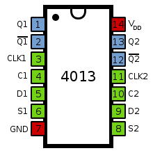
As you can see in this picture, the CD4013BE Integrated Circuit (IC) I used, consists of actually 2 Flip Flops from which our traffic light needs only one.
- Pins 1 / 2: These are the actual outputs (Q1, !Q1) of the Flip Flop and therefore are responsible for turning the LEDs on and off.
- Pin 3 is actually intended to be connected to a clock and each time such a clock triggers, it evaluates the Flip Flop’s inputs and sets its outputs (Q1, !Q1). In our case we connect it to the toggle switch which then serves as the clock signal, meaning that pressing it triggers mentioned behavior.
- Pins 4 / 6: Are the Set and Reset inputs of the Flip-Flop. We don’t use these and connect them to ground (GND).
- Pin 5 gets its input from Pin 2 (!Q1) and is actually responsible for flipping the current state of the Flip Flop.
- Pin 7 is connected the ground (GND).
- Pin 14 is connected to 5V Power (VIN).
For a good explanation on the the workings of this Flip Flop (and a truth table of its states) go here.
Putting Things Together
Now I had a working proof of concept on breadboard and needed to put (solder) things together.
- This is the Flip Flop soldered onto circuit board that I cut as small as I needed it to be.
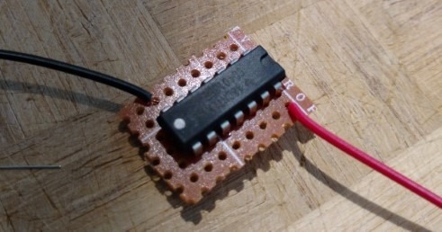
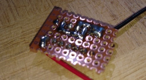
- I tried to reduce the amount of wires and soldered all the pins which needed ground (GND) connection directly on the circuit board.
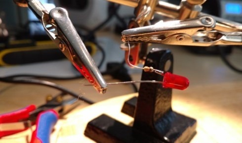
- To save even more space, I soldered the LED protective resistors directly to the LEDs.
- The case of the traffic light, I made out of Lego plates (from which I have literally dozens because of my mini figure collection craze).
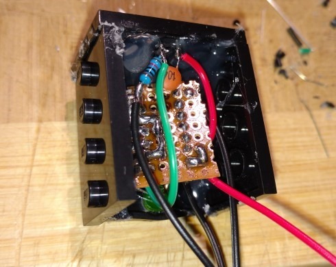
- The toggle switch is built into the top Lego plate and soldered directly to the pull-down resistor and the debounce capacitor.
- Everything is held together by hot glue.
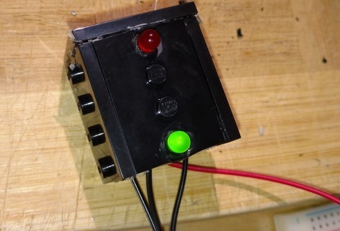
The Final Outcome
The only thing missing now was the power supply. For that I simply used one of the battery cases for 3 x 1.5 V AAA batteries and led the cables through a plastic column to the case. Again hot glued everything together and the traffic light was ready.
Needless to say, my son really likes his new toy :-)
