Making a Ghostbusters Proton Wand
April 18, 2020The Story So Far
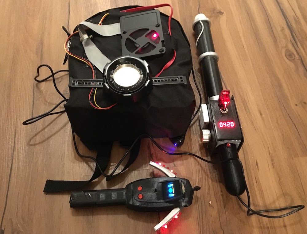
Last year, my wife and I made a Ghostbusters costume for our (then) 6-year-old, for his kindergarten carnival party. I found this PKE Meter on Thingiverse which I built for this costume and for the proton wand and backpack, I designed, 3D-printed and soldered something myself. I was quite happy with the result.
A few weeks ago, my now 7-year-old discovered these toys again which triggered an immediate "Why don't I have that, Daddy!" reaction in my 3-year-old. Needless to say that my "Well, last year you were too young and didn't actually care" response was not received particularly well and I was given a 1-week ultimatum to make him a proton wand as well.
So, why not. I dug out my 3D models, notes, sketches and figured that this would be a good opportunity to write this blog post I should have written last year anyway.
I was given a 1-week ultimatum by my 3-year-old to make him a proton wand as well.
The Parts
All the main parts of the proton wand come out of the 3D printer. I designed and made them available on Tinkercad.
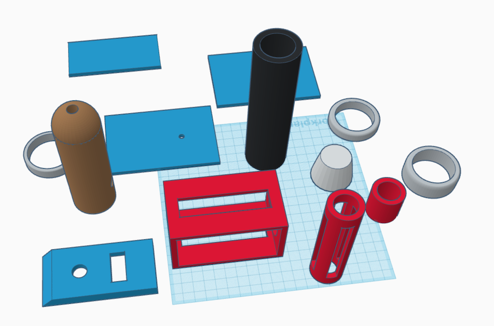
The only 2 parts I did not design myself and found on Thingiverse, were the heat sink and the regulator knob.
These are the parts fresh out of my 3D printer.
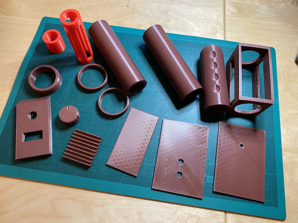
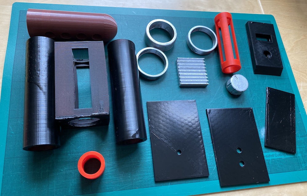
All the visible parts (except for the handle) got a treatment with black or silver acrylic spray.
Part List
In addition to those 3D-printed parts, you will need this:
- Arduino Nano
- USB power bank
- 5x WS2812b LEDs (RGB, individually addressable)
- Potentiometer
- On/Off Switch (with indicator LED)
- TM1637 4-digit 7-segment display
- Round push button
- LED
- 330Ω Resistor
- On/Off Switch
- Piezo Speaker
- Cables, wires
Power
For the power supply I am just using a regular power bank like you would use for charging a phone. This power bank disappears in the backpack and the proton wand is connected to it using a USB cable coming out of the handle.
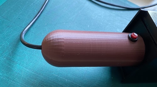
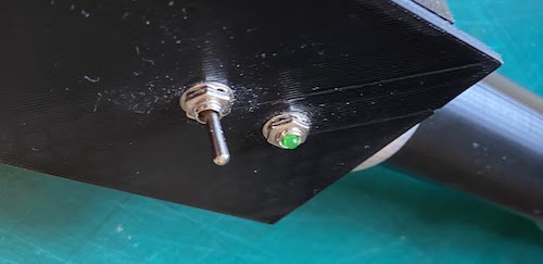
On/Off Switch
The main on/off switch sits on top of the wand's casing and interrupts the Arduino's power supply. I chose an extra fancy switch for that, that comes with a safety cap which must be opened first. This makes activating the wand look really legit and serious - my kids love that feature.
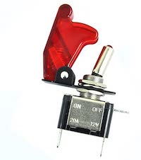
Also, this switch has a built-in led that indicates whether the wand is on or off.
Trigger Button
The fire/trigger button is also integrated in the proton wand's handle and is a simple push-button connected to the Arduino's digital pin 2 (see FIRE_BUTTON_PIN in Firmware).
Intensity Control
As soon as the trigger button is active, another component comes into play which is the intensity regulator. This is a simple potentiometer connected to the Arduino's analog pin (A1).
The value set by this potentiometer gets displayed on the 4-digit-7-segment display. It also affects the proton wand's light and sound output to make this toy more interactive.
Display
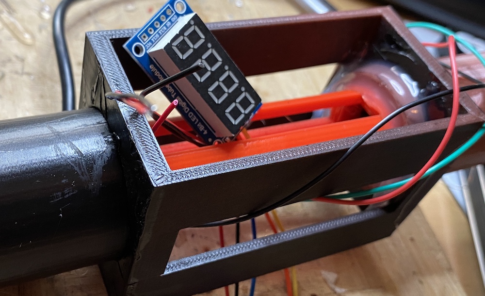
For displaying the potentiometer's state I used a 4-bit-7-segment LED display that sits in front of the main power switch.
Note: I'm using a 5-pin version of this display which is apparently outdated and rather hard to come by. You are more likely to find a 4-pin I2C version of this. This however means that the firmware needs to be updated accordingly.
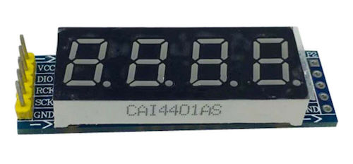
This display uses another 3 digital pins of the Arduino.
| Arduino Pin | Display Pin | Firmware constant |
|---|---|---|
| 6 | SCK | SHIFTCLOCK |
| 4 | RCK | LATCHCLOCK |
| 3 | DIO | DISPLAYOUT |
| GND | GND | - |
| VCC | VCC | - |
Light
The proton wand's tip is 3D-printed with translucent filament and accommodates 5 individually-addressable WS2812b RGB LEDs. The last LED in this strip is glued flat to the bottom of the tip and the remaining 4 form a circle glued to the inner wall of it.
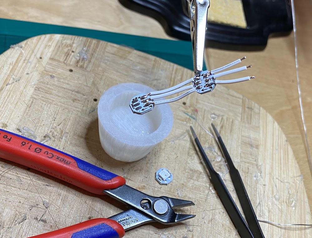
In addition to power and ground, this LED strip only needs one other digital pin on the Arduino for its data signal (see LIGHT_PIN in Firmware).
Pushing the trigger button activates this light strip, hence creating the firing effect and the potentiometer setting determines its color and intensity.
Sound
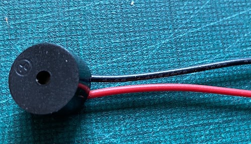
Of course, a toy like this also needs a high-pitched, nerve-wracking sound effect when the trigger button is pressed. This is accomplished by a small piezo speaker that gets connected to pin 9 on the Arduino (see AUDIO_PIN in Firmware). Similar to the light effects, the frequency of the audio signal, is also determined by the potentiometer ("intensity control").
However, even more important than having sound-effects, is the ability to turn them off again from time to time (you're welcome fellow parents). For this, another on/off switch is added to the side of the proton wand's main casing. This button's state is read via digital pin 7 on the Arduino (see AUDIO_ONOFF_BTN_PIN in Firmware). Another LED connected to pin 8 (see AUDIO_ONOFF_LED_PIN) visualizes the on/off state off the audio.
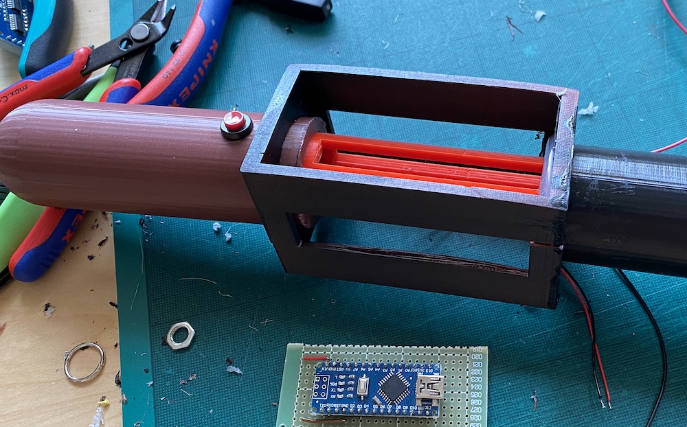
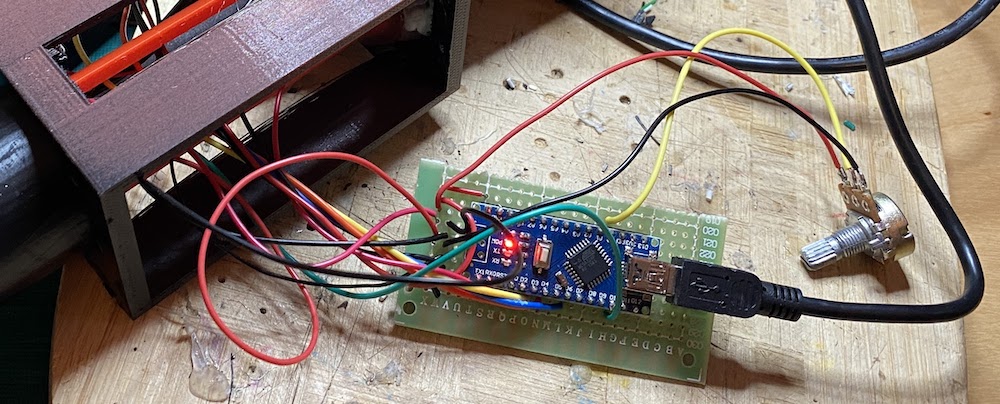
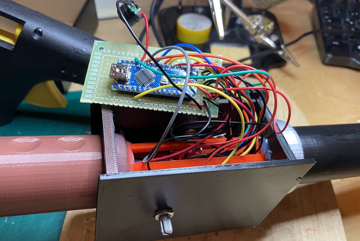
Assembling The Parts
After soldering and gluing all parts together this is nearly finished.
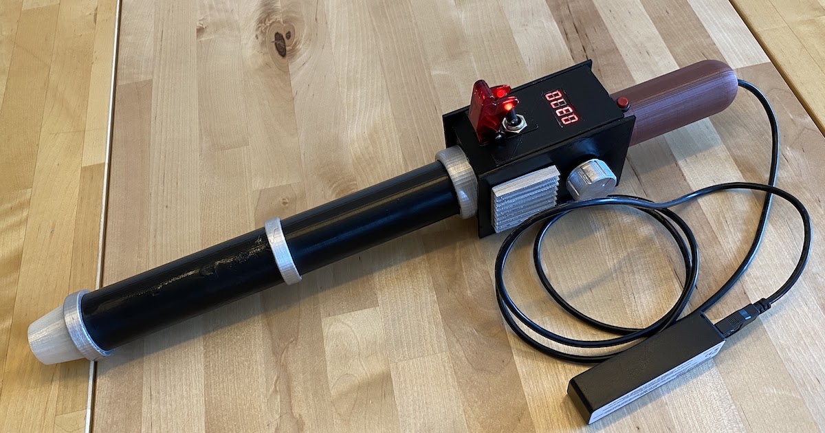
After Cramming all the cables in, closing the main case up and attaching the last parts (knob and heatsink), this is how the end-result looks like.
Firmware
Following Arduino sketch is the proton wand's "firmware". Most part of this code just deals with showing numbers on the 4-digit-7-segment display and displaying sound in real-time. The "actual logic" is only a few lines of code in the main function that:
- Reads the potentiometer and calculates an intensity setting (
level) from it - Checks if the wand is firing (
digitalRead(FIRE_BUTTON_PIN)) - If yes:
- Activates the RGB LEDs (
strip.setPixelColor) - Checks is sound is enabled ('digitalRead(AUDIO_ONOFF_BTN_PIN`):
- If yes:
- Plays sound ('NewTone`)
- Activates the RGB LEDs (
- If no:
- Turn off LEDs (
strip.clear())
- Turn off LEDs (
Note: For controlling the RGB LEDs, the Arduino 3rd party library
Adafruit_NeoPixelis used.
This is the full source code of the sketch.
#include <Adafruit_NeoPixel.h>

#define LIGHT_PIN            10
#define FIRE_BUTTON_PIN       2
#define NUM_DIGITS            4
#define SHIFTCLOCK            6
#define LATCHCLOCK            4
#define DISPLAYOUT            3
#define AUDIO_ONOFF_BTN_PIN   7
#define AUDIO_ONOFF_LED_PIN   8
#define AUDIO_PIN             9


Adafruit_NeoPixel strip(5, LIGHT_PIN, NEO_GRB + NEO_KHZ800);
const uint32_t WHITE = strip.Color(255, 255, 255);
const uint32_t colors[] =
{
  strip.Color(  0,   0, 255), // blue
  strip.Color(  0, 255,   0), // green
  strip.Color(255, 255,   0), // yellow
  strip.Color(255, 165,   0), // orange
  strip.Color(255,   0,   0), // red
};
byte printDigits[NUM_DIGITS] = {0};

void setupDisplay()
{
  // configure outputs:
  pinMode(SHIFTCLOCK, OUTPUT);
  pinMode(LATCHCLOCK, OUTPUT);
  pinMode(DISPLAYOUT, OUTPUT);

  // setup timer code

  // Timer 2 - gives us the display segment refresh interval

  TCCR2A = 0;  // reset Timer 2
  TCCR2B = 0;
  TCCR2A = bit (WGM21) ;   // configure as CTC mode

  // 16 MHz clock (62.5 nS per tick) - prescaled by 256
  //  counter increments every 16 µS.
  // There are 8 segments and 4 digits to scan every 1/60th of a second
  // so we count 32 of them at 60Hz, giving a display refresh interval of 512 µS.
  #define scanRateHz 60  // tested, maximum that works is 88 using Wire library and Serial
  #define NUM_DIGITS 4
  #define displayScanCount 1000000L / NUM_DIGITS / 8 / scanRateHz / 16

  OCR2A  = displayScanCount;            // count up to 32 @ 60Hz

  // Timer 2 - interrupt on match (ie. every segment refresh interval)
  TIMSK2 = bit (OCIE2A);   // enable Timer2 Interrupt
  TCNT2 = 0;  // counter to zero

  // Reset prescalers
  GTCCR = bit (PSRASY);        // reset prescaler now
  // start Timer 2
  TCCR2B =  bit (CS21) | bit (CS22) ;  // prescaler of 256
}

void setup()
{
  setupDisplay();
  strip.begin();
  pinMode(FIRE_BUTTON_PIN, INPUT_PULLUP);
  pinMode(AUDIO_ONOFF_BTN_PIN, INPUT_PULLUP);
  pinMode(AUDIO_ONOFF_LED_PIN, OUTPUT);
}

uint16_t currentPixel = 0;

uint32_t levelToColor(uint32_t level)
{
  auto index = map(level, 0, 100, 4, 0);
  return colors[index];
}

void loop()
{
  int level = analogRead(A0);
  level = min(100, max(0, map(level, -1, 1024, 0, 101)));
  auto currentDelay = max(20, level);

  bool soundOn = false;
  bool isFiring = (digitalRead(FIRE_BUTTON_PIN) == 0);
  bool isAudioOn = (digitalRead(AUDIO_ONOFF_BTN_PIN) == 0);
  digitalWrite(AUDIO_ONOFF_LED_PIN, isAudioOn);
  if (isFiring) {
    if (isAudioOn) {
      NewTone(AUDIO_PIN, 2500 - level, currentDelay / 2);
    }
    strip.setPixelColor(4, currentPixel % 2 == 0 ? levelToColor(level) : 0);
    for (uint16_t i = 0; i < 4; i++) {
      strip.setPixelColor(i, i == currentPixel ? levelToColor(level) : 0);
    }
    currentPixel = (currentPixel + 1) % 4;
    if (currentPixel % 2 == 0) {
      strip.setPixelColor(currentPixel, WHITE);
    }
    strip.show();
  }
  else
  {
    strip.clear();
    strip.show();
  }

  delay(currentDelay);

  showNumber(1000 - level * 10);
}

void showNumber(int val)
{
  for (int i = 3; i >= 0; i--)
  {
    printDigits[i] = val % 10;
    val /= 10;
  }
}

//
// display update ISR
//
// every time this routine is called, 16 bits are shifted into the display
// and latched.
// The first 8 bits is the segment data, and first 4 bits of the second byte are
// the segment select.
ISR (TIMER2_COMPA_vect)
{
  // segment list to make a seven segment font

  const byte NUM_PLUS_SYMBOL_FONT[] = {
    0b00111111, // 0
    0b00000110, // 1
    0b01011011, // 2
    0b01001111, // 3
    0b01100110, // 4
    0b01101101, // 5
    0b01111101, // 6
    0b00000111, // 7
    0b01111111, // 8
    0b01101111, // 9
  };

  static byte digit = 0;
  static byte segment = 0x80;
  byte tempDigit = printDigits[digit];

  // send segment data
  shiftOut(DISPLAYOUT, SHIFTCLOCK, MSBFIRST, ~(segment & ((NUM_PLUS_SYMBOL_FONT[tempDigit & 0x7f]) | (tempDigit & 0x80))) );

  // send digit select data
  shiftOut(DISPLAYOUT, SHIFTCLOCK, MSBFIRST, 8 >> digit);

  // data is now in the display shift register, so latch to LEDs
  digitalWrite(LATCHCLOCK, LOW);
  digitalWrite(LATCHCLOCK, HIGH);

  // increment variables to select the next segment and possibly the next digit:
  //
  segment = segment >> 1;
  if (segment == 0)
  {
    segment = 0x80;
    digit++;
    if (digit >= NUM_DIGITS)
    {
      digit = 0;
    }
  }
}

unsigned long _nt_time;       // Time note should end.
uint8_t _pinMask = 0;         // Pin bitmask.
volatile uint8_t *_pinOutput; // Output port register

void NewTone(uint8_t pin, unsigned long frequency, unsigned long length) {
  uint8_t prescaler = _BV(CS10);                 // Try using prescaler 1 first.
  unsigned long top = F_CPU / frequency / 4 - 1; // Calculate the top.
  if (top > 65535) {                             // If not in the range for prescaler 1, use prescaler 256 (61 Hz and lower @ 16 MHz).
    prescaler = _BV(CS12);                       // Set the 256 prescaler bit.
    top = top / 256 - 1;                         // Calculate the top using prescaler 256.
  }

  if (length > 0) _nt_time = millis() + length; else _nt_time = 0xFFFFFFFF; // Set when the note should end, or play "forever".

  if (_pinMask == 0) {
    _pinMask = digitalPinToBitMask(pin);                    // Get the port register bitmask for the pin.
    _pinOutput = portOutputRegister(digitalPinToPort(pin)); // Get the output port register for the pin.
    uint8_t *_pinMode = (uint8_t *) portModeRegister(digitalPinToPort(pin)); // Get the port mode register for the pin.
    *_pinMode |= _pinMask; // Set the pin to Output mode.
  }

  ICR1    = top;                     // Set the top.
  if (TCNT1 > top) TCNT1 = top;      // Counter over the top, put within range.
  TCCR1B  = _BV(WGM13)  | prescaler; // Set PWM, phase and frequency corrected (ICR1) and prescaler.
  TCCR1A  = _BV(COM1B0);
  TIMSK1 |= _BV(OCIE1A);             // Activate the timer interrupt.
}

void noNewTone(uint8_t pin) {
  TIMSK1 &= ~_BV(OCIE1A);   // Remove the timer interrupt.
  TCCR1B  = _BV(CS11);      // Default clock prescaler of 8.
  TCCR1A  = _BV(WGM10);     // Set to defaults so PWM can work like normal (PWM, phase corrected, 8bit).
  *_pinOutput &= ~_pinMask; // Set pin to LOW.
  _pinMask = 0; // Flag so we know note is no longer playing.
}

ISR(TIMER1_COMPA_vect) { // Timer interrupt vector.
  if (millis() >= _nt_time) noNewTone(0); // Check to see if it's time for the note to end.
  *_pinOutput ^= _pinMask; // Toggle the pin state.
}
Let's Hunt Some Ghosts
All done - my little Ghostbusters approve!