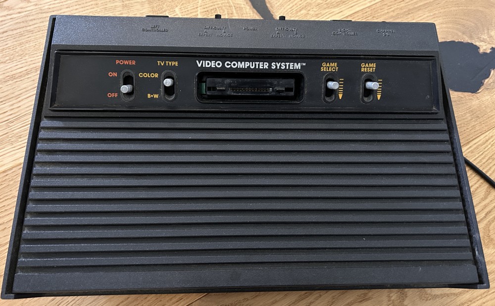
The Atari 2600 Composite Video Mod
June 14, 2024A few months ago, I blogged about adding the composite video mod to an Atari 2600 Junior. These instructions are for the original Atari VCS (later just called Atari 2600). The process is similar and I bought and used the same mod kit for it. Here are the details.
Opening the Case
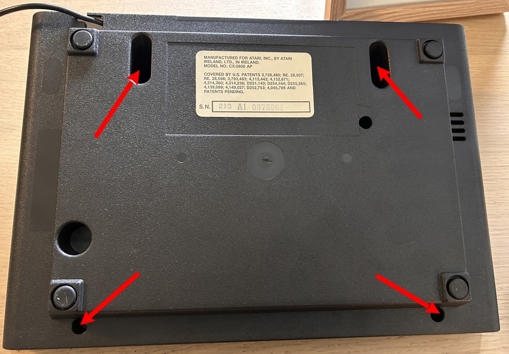
The case is held together by 4 screws in the back. Simply remove them and the case opens easily. You can then disconnect the antenna cable and lift the board out of the case.
Removing the RF Shielding
Similar to the 2600 Junior, there's an RF shielding case around the processor and chips. Use a pair of pliers to loosen the clamps and remove the shielding.
Removing Components
First, we need to get rid of the RF modulator box (at the bottom right of the mainboard) and the vertical circuit board to the left of it. Use a soldering iron or (even better) an unsoldering tool for that.
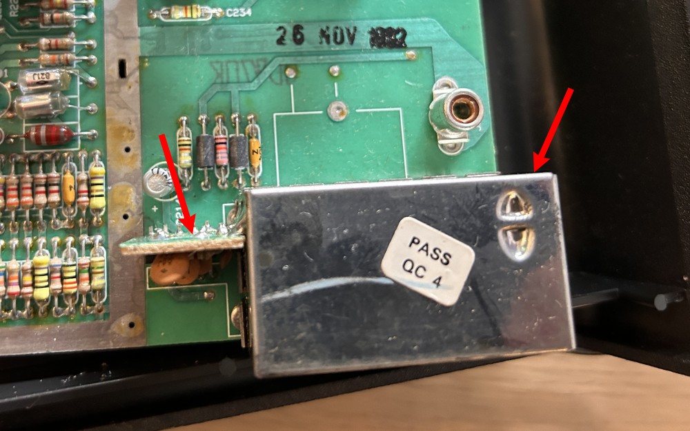
This is how it looks like after you removed those.
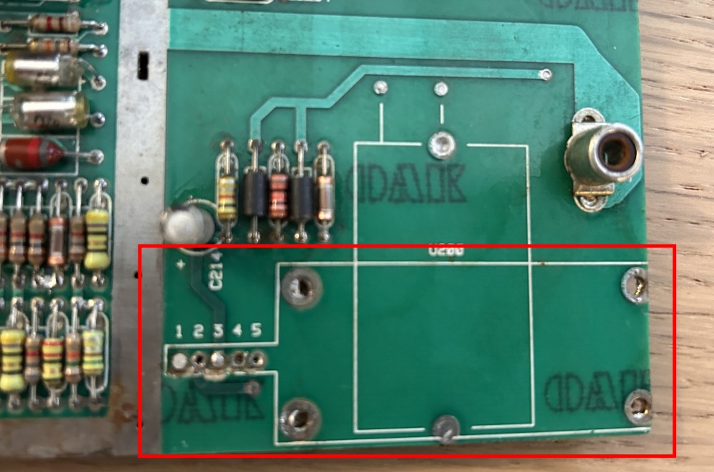
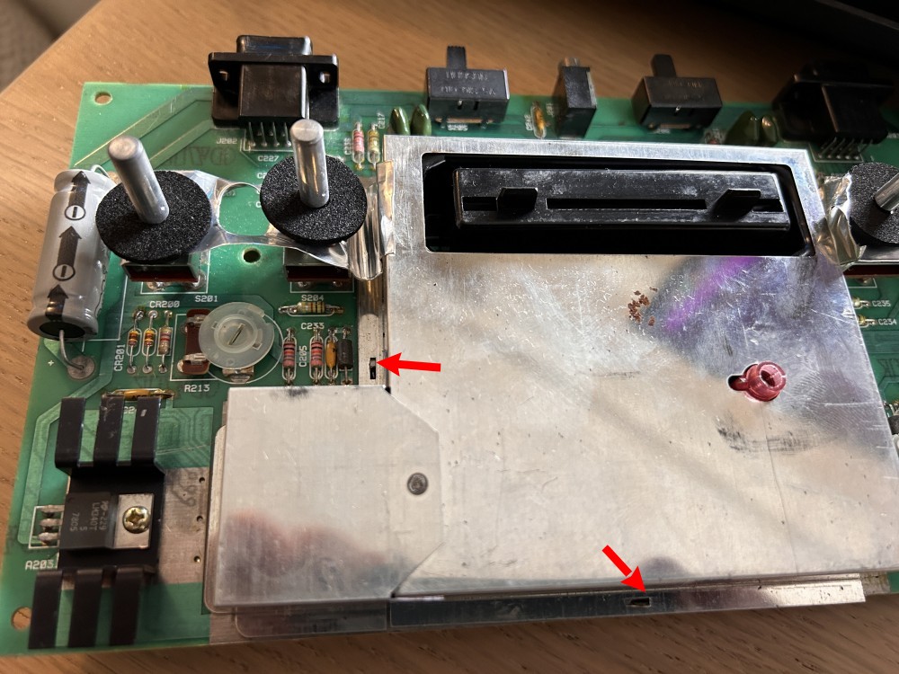
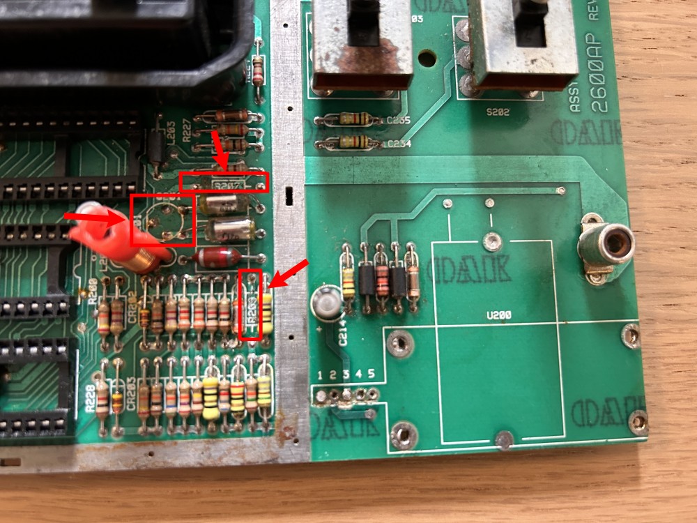
As a next step, we have to remove three electronic components, two resistors (R207, R209) and on transistor
(Q201). The image below shows the - now empty - spots on the mainboard.
Installing the RFA Connectors
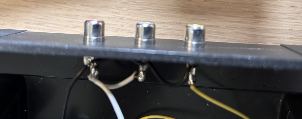
A good spot for the RFA (cinch) connectors is the long side of the case facing away from you. I drilled the wholes, put the connectors in place and wired them up. Ground (black) connects to all 3 RCAs. Video (yellow) connects to the yellow connector and Audio (white) connects to both the red and the yellow connector.
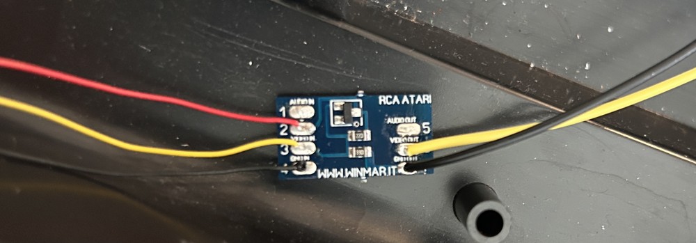
Connecting the RCA Module
Now it's time to install the mod kit circuit board (RCA module). First, I soldered some wires to the board (make sure to leave those long enough for later maintenance). This is the color-coding I used.
Input:
| Pin | Color |
|---|---|
| VIN | red |
| Video | yellow |
| GND | black |
Output:
| Pin | Color |
|---|---|
| Video | yellow |
| GND | black |
Note: Audio (white) is just pass-through, so I soldered ot directly to the RFA connectors (see below). You can route it via this board as well though, if you prefer.
Then connect VIN, Video and GND to the mainboard where you unsoldered the vertical RF circuit board before. GND goes to pin 1, VIN to pin 3 and Video to pin 4.
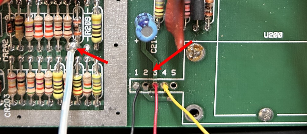
For Audio, connect (solder together) the two components left to the empty spot where R209 was and solder the white
wire to this joint. The other end of the wire goes directly to the RFA connector.
Finally, the output pins of the mod board must be connected to the RFA connectors.
Closing it Back Up
Make sure to fix the mod kit board and the cables into place (I used hot glue) and close the box back up.
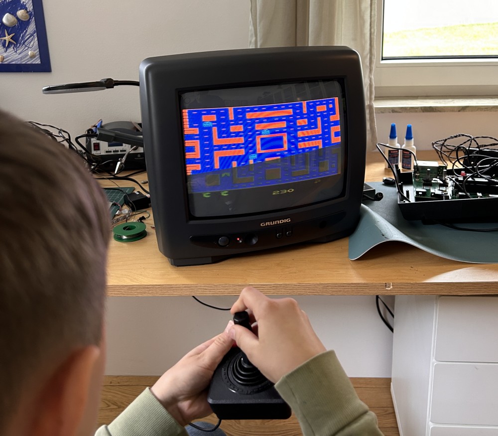
Time to play some Atari! 🤩