Arduino LED Picture Frame
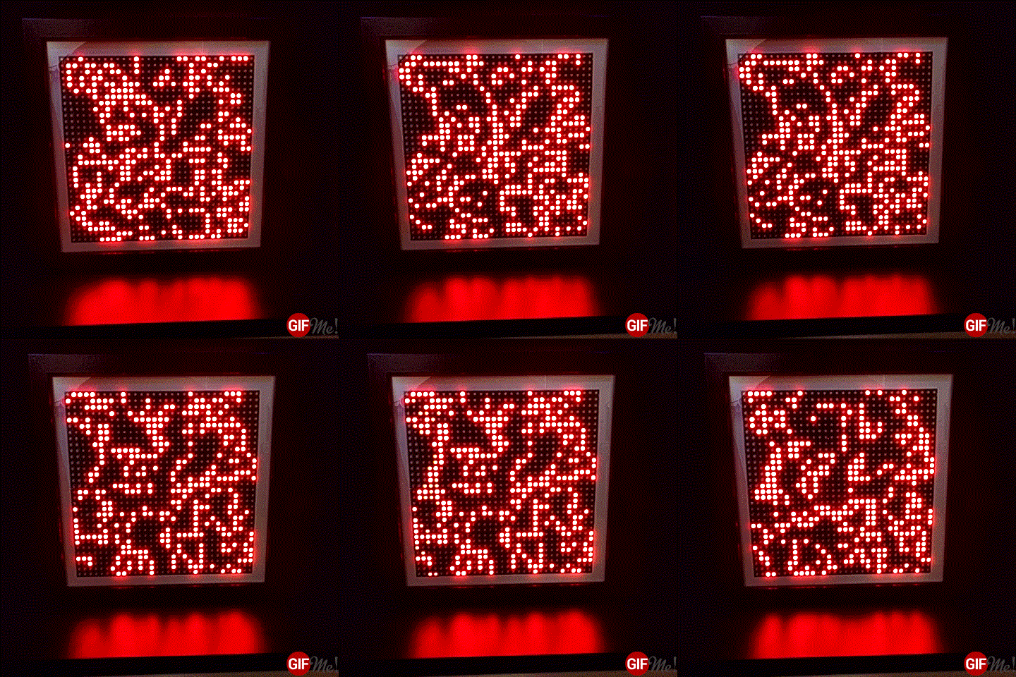
December 20, 2016A while ago, I made an LED picture frame that would display a Game of Life simulation.
This cellular automaton is among the simplest yet most fascinating simulations possible. Its seeming vividness that emerges from the most basic set of instructions has kept me in awe ever since I first read about it. Its ever evolving, ever changing patterns made it the perfect candidate for the first content being featured on my LED display frame.
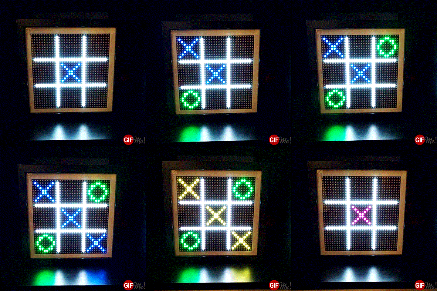
Over time I added two other simulations to make this decorative object a bit more interesting. The first simulation was a game of Tic Tac Toe (which I will forever associate with the movie War Games, that ranks among my all-time favorites and has influenced my life to a great deal).
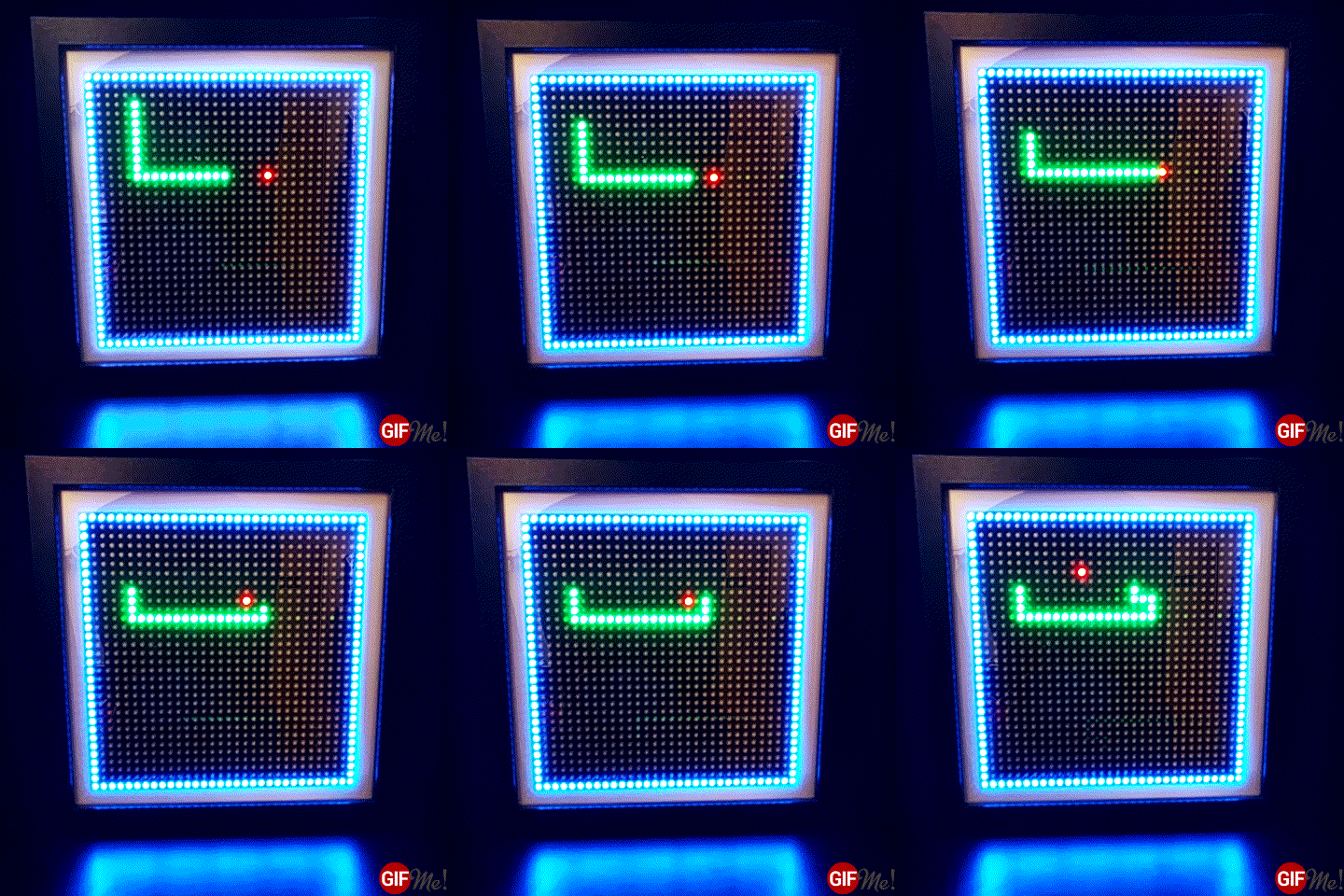
The other one was Snake, which is both the first mobile phone game I ever played and also the one I probably spent most hours playing.
What’s still missing from this collection of all time classics is Tetris, which is another game is spent hours and hours playing.
Assembling the Frame
This is the list of parts and components used to build the frame:
- Adafruit 32x32 RGB LED Matrix Panel: This matrix panel comes fully assembled and is ready to go.
- Arduino Mega: The reason this simulation is running on an Arduino Mega (and not a Uno or Nano, which I usually use) are memory constraints. The Mega offers a lot more memory and it’s way easier to keep copies of the matrix data around.
- Arduino Proto Shield: I used a proto shield to connect the matrix ribbon cable and the GPIO pins. This provides a bit more flexibility but you can also connect / solder the wires directly.
The wiring itself is not too complicated. You can find good instructions directly on the Adafruit product page. - 2 IKEA RIBBA picture frames: I used 2 frames glued together in order to get enough depth to easily accommodate the matrix, the Arduino, the shield and all the cables. You could maybe get by with only one frame if you cram things together, but why bother actually?
- 5V / 3A power supply. You should get away with a 2 ampere power supply but I wanted to be safe here.
- On / Off switch: I added a dedicated power switch to the frame’s back plate. That way I can keep the power supply connected all the time. You can omit this, of course.
- Reset button: Again, this is optional. But I wanted a quick way to reset the simulation (mainly for testing purposes).
- USB cable: This cable protruding from the back plate allows for quick software updates and without the need to disassemble the frame.
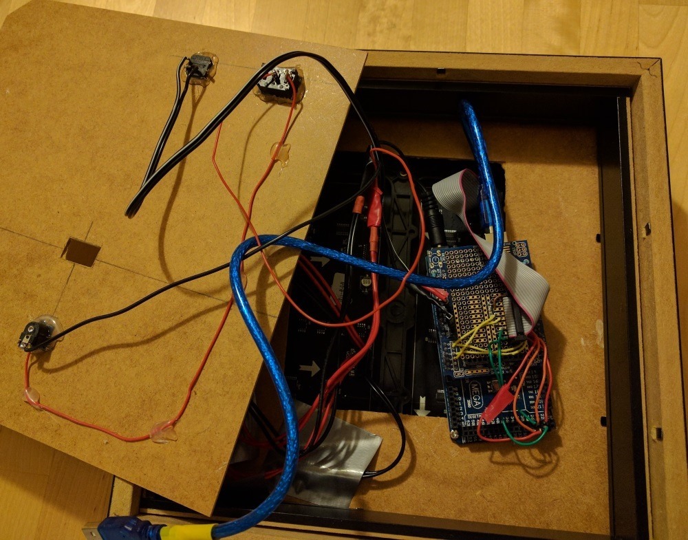
That’s what the assembled frame looks like (back and front).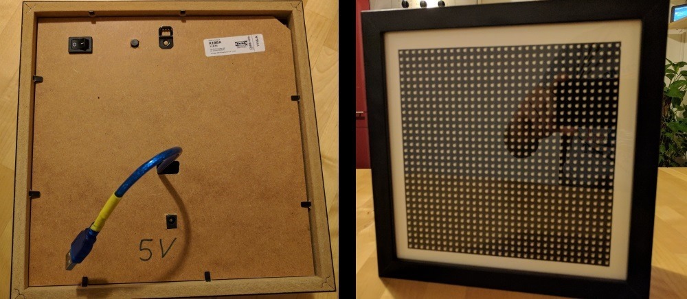
The Software
The software is based on these 2 Adafruit libraries, so you have to go and install them first.
- RGB Matrix Panel: This library provides the low-level code specific for this LED panel.
- Adafruit GFX Library: This library provides generic higher-level operations for all kinds of Adafruit LED hardware.
The code I wrote for displaying these simulations can also be found on GitHub.
https://github.com/z1c0/LedMatrix
It’s badly documented and still a work in progress but also it’s not too complicated.
Clone it, fork it, send me pull requests … I appreciate it!
