Serial Debugging on Arduino
October 20, 2015Debugging an Arduino sketch usually happens in a way that is often referred to as “printf debugging”. It commonly works like this:
printf("here 1");

foo();

printf("here 2");

bar();

printf("here 3");
Let’s admit it, we all have written that kind of code. It’s not elegant, it’s not pretty but it often gets the job done. Especially on devices like Arduino where we normally deal with short sketches, printing information about the program’s state works reasonably well. But how can we receive this data?
Using Serial Monitor
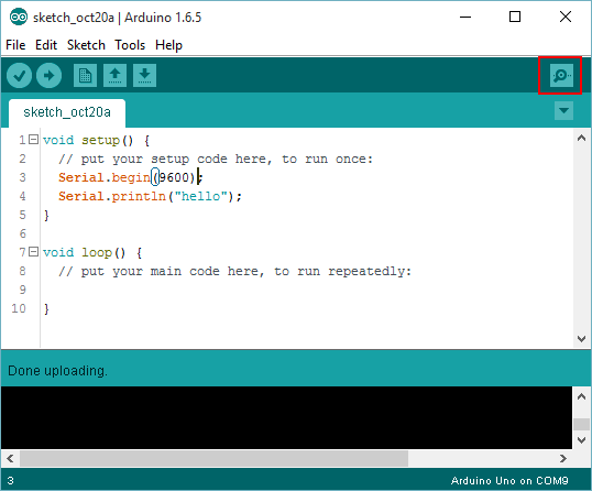
Since Arduinos usually don’t come with a display where output can go to, we usually use serial (COM) communication to receive debug output. This is pretty straight forward through the Serial API. All we need to do is open the Serial port at a specified baud rate.
Serial.begin(9600);
Then we can output data like this.
Serial.println("hello");
This data now gets sent over USB to the connected PC. This is enabled by the UART device on the Arduino’s chip.
UART enables serial communication over USB.
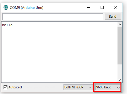
To receive this data while the sketch is running, we need to open Serial Monitor on the Tools menu (shortcut Ctrl+Shift+M). All you need to check now is that the baud rate is set to the same value as we specified in the script (9600 in our case).
Generally, this is pretty useful. A problem arises though if we connect the RX / TX pins (pins 0 and 1) of the Arduino to another device or shield. Connecting and thus blocking these pins means we now cannot use the serial over USB communication through the UART mechanism any more.
Serial over USB is not available if the Arduino’s RX / TX pins are used.
So how can we debug (or rather print information from) our sketch now?
SoftwareSerial to the Rescue!
Luckily, there is a simple solution readily available for this scenario in the form of the library SoftwareSerial.
With the help of this library we can select two different GPIO pins and use them for emulated serial communication. The API is very similar to the original Serial API.
We need to include a header file first.
#include <SoftwareSerial.h>
Then create a SoftwareSerial instance and specify the GPIO pins that will be used as RX / TX pins.
SoftwareSerial softSerial(10, 11); // RX, TX
Again, we have to specify a baud rate for communication:
softSerial.begin(9600);
And then send data.
softSerial.println(“Hello SoftwareSerial”);
How can we receive this data?
Still we cannot simply receive the data using Serial Monitor, since it is expecting data from the actual UART RX / TX pins. So we basically have three options, two of them involving additional hardware.
Option 1: Use SoftwareSerial for hardware communication
This means if your actual serial RX / TX pins are allocated by some hardware device but you also need to to write output to the debug monitor, use SoftwareSerial for the hardware device and send your debug information to the actual serial port.
This is a nice and easy solution, but it might not work in all cases. I e.g. had problems using SoftwareSerial for communication with the ESP2866 WIFI module. I just would not get reliable communication unless I switched back to hardware serial. That left me with options 2 and 3.
Option 2: Use another Arduino
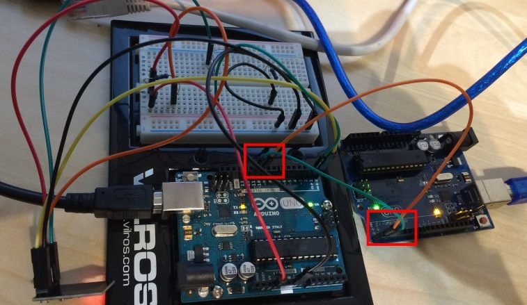
This is pretty simple as well. Usually, if you are tinkering with these devices you always have one or two (or dozens) of spare Arduinos at hand. So all you have to do is connect the SoftwareSerial GPIO pins of the first Arduino, to the RX / TX pins of the second one. Then make sure you have the right COM port selected (!) in Arduino Studio and open Serial Monitor for receiving data.
This picture shows this option in action. We can see that RX / TX pins are occupied by the WIFI module and how SoftwareSerial pins 10 / 11 are connected to the RX / TX pins of another Arduino Uno.
Option 3: Use an USB UART adapter
In case you have an USB UART adapter (or want to order one for 5-10€) this is also a really easy way of getting debug output from SoftwareSerial.
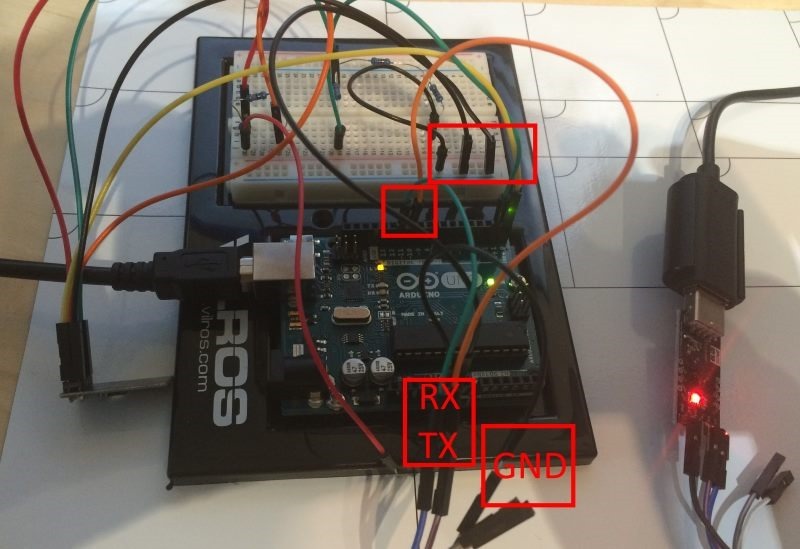
Simply connect SoftwareSerial pins to the RX / TX pins oft the USB UART adapter and also make sure you connect the ground (GND) pins.
This picture again shows how the wiring is done.
Now, all you need to do is connect the USB device to a PC and receive the data there.
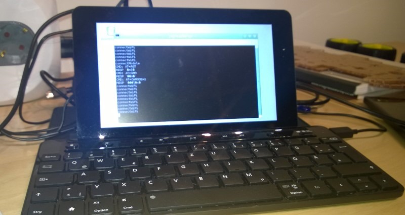
I usually use the RaspberryPi on my desktop and the screen command to get this done.
$ screen /dev/ttyUSB0 9600
I hope that helped.
