Controlling an RGB LED Strip using an Arduino - Part 1
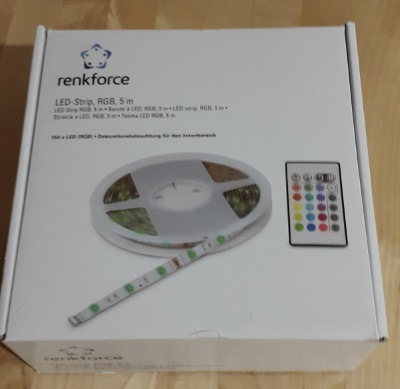
October 5, 2015I recently bought one these RGB LED strips, that are relatively cheap (~ 30€ for 5m) and even come with an IR sensor and a remote control.
Since I had no other plans for it, I decided to tape the strip (self-adhesive: nice) to the back of my TV (actually the "TV cupboard") to have some pleasant ambient lighting when watching TV.
This brought up two problems though:
- First, I really didn't like the idea of yet another remote control in my living room. Especially, since I am routing the TV signal through my Xbox One and hand therefore been able to actually reduce remote control complexity to just the Xbox One remote.
- But the second, and more important problem, was that the mentioned Xbox One remote control was constantly interfering with the LED strip’s remote. This had me inadvertently turning the LED strip off, on or change its colors randomly when navigating the
Xbox One’s menus or simply switching channels.
So I decided to replace the IR remote control with an Arduino based solution that let me control the LED strip through a small web application.
Part List
That’s the hardware needed for this project.
- Breadboard
- Cables
- 12 Power Supply
- RGB LED Strip
- Arduino Nano
- ENC28J60 Ethernet module
- 3 x TIP120 NPN Transistors
- 3 x 330 Ohm Resistors
Step 1 - Connectivity:
Most Arduino boards do not come with built-in network interfaces, so I had to solve this "problem" first. On Amazon, I found the ENC28J60 Ethernet module for the Arduino which seemed quite popular and well supported in terms of examples and documentation available online.
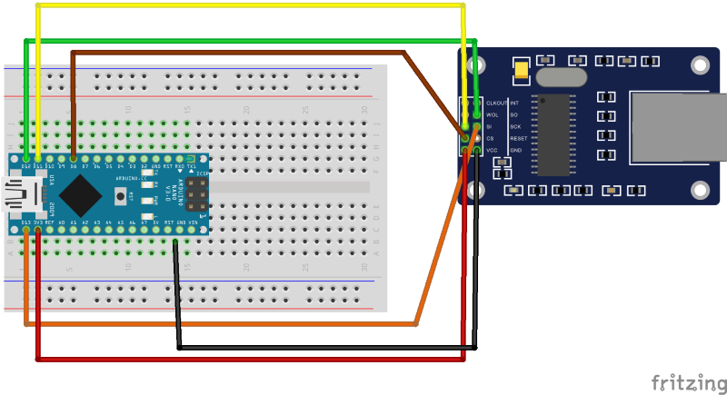
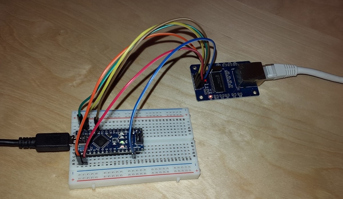
Check out my previous blog post on wiring and programming the ENC28J60 Arduino Ethernet module.
Wiring the ENC28J60 module is no big deal, the only thing you have to take care of is using the Arduino’s 3V output as power supply for the module. Operating the IO pins with 5V seems to be OK though. All the examples I found are wiring directly to the Arduino’s GPIO pins.
Running the ENC28J60 with 5V power will kill the module in the long term!
Step 2 - A Voltage Problem and Transistors
Arduinos operate on 5V, the LED strip on 12V!
The main challenge here was having to deal with two different voltages since the Arduino operates using 5V and the LED strip needs 12V to work.
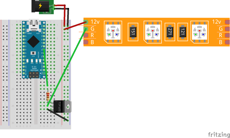
That means I could not just use the Arduino's IO pins to regulate the RGB channels of the LED strip but I needed transistors (e.g. TIP120 NPN) which would serve as dim switches for my purpose. Using these transistors I could then use the Arduino's 0V - 5V pin outputs to regulate voltage input for the LED strip between 0V and 12 V.
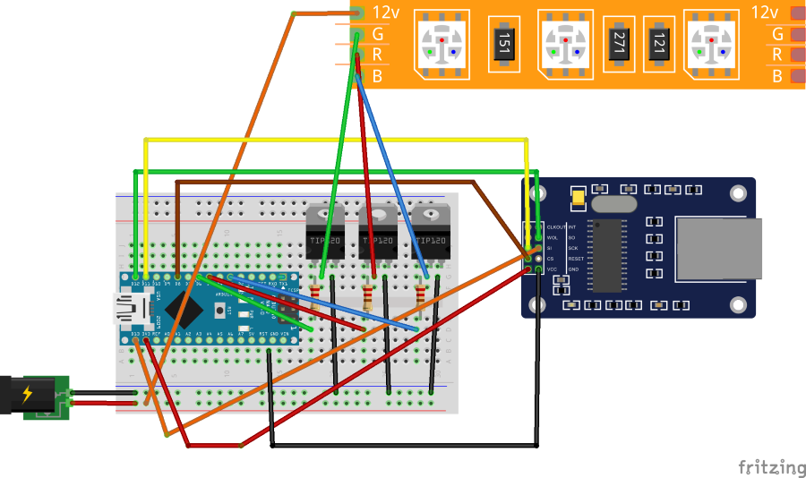
Following schematic shows how its done for one (green) color channel. Red and blue need to be wired the same way.
Luckily, the Arduino’s power supply has a built in voltage regulator so we can power it from the same source as the LED strip, which makes things easier.
The Arduino and the LED strip can share the 12V power supply.
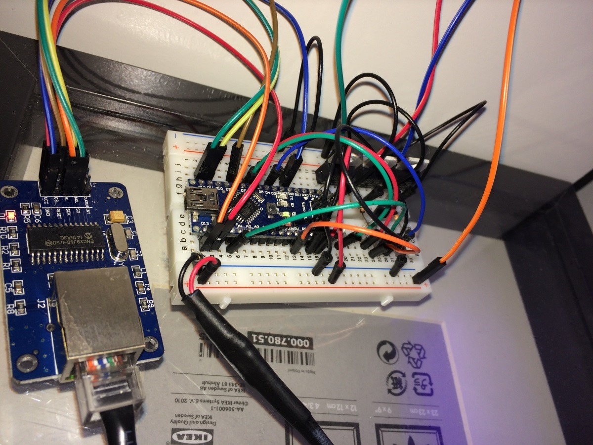
Here’s the fully wired project:
Step 3 - The Software
I wanted to keep the software as simple as possible as far as the Arduino sketch was concerned. While it would have been entirely possible to host a "color chooser" web application on the Arduino itself, I figured this was not the best way to implement that. I dumbed the solution down to a very simple URL based web service that would accept RGB color values:
e.g. http://<ARDUINO_IP_ORHOSTNAME>?r=255&g=0&b=0
This would give me more flexibility to create a nice little web interface on another device (e.g. the PC or RaspberryPi in my office) that could then send HTTP GET requests to the Arduino thus setting the LED strip's RGB values.
Following code snippet shows the whole code which is necessary to handle the incoming RGB requests and set the Arduino’s output pins accordingly. The source code can also be found on GitHub.
#include <EtherCard.h>

#define B_PIN 3
#define R_PIN 5
#define G_PIN 6

static byte mymac[] = { 0x74, 0x69, 0x69, 0x2D, 0x30, 0x31 };
static byte myip[] = { 192, 168, 1, 45 };

byte Ethernet::buffer[500];
BufferFiller bfill;

const char HttpNotFound[] PROGMEM =
  "HTTP/1.0 404 Unauthorized\r\n"
  "Content-Type: text/html\r\n\r\n"
  "<h1>404 Page Not Found</h1>";


void setup ()
{
  if (ether.begin(sizeof Ethernet::buffer, mymac) == 0)
  {
    Serial.println("Failed to access Ethernet controller");
  }
  ether.staticSetup(myip);
}

static word HomePage(byte r, byte g, byte b)
{
  bfill = ether.tcpOffset();
  bfill.emit_p(PSTR(
    "HTTP/1.0 200 OK\r\n"
    "Content-Type: application/json\r\n"
    "Pragma: no-cache\r\n"
    "\r\n"
    "{ 'red': $D, 'green': $D, 'blue': $D }"), r, g, b);
  return bfill.position();
}

int r = 0;
int g = 0;
int b = 0;

void loop ()
{
  word len = ether.packetReceive();
  word pos = ether.packetLoop(len);
  if (pos)  // check if valid tcp data is received
  {
    bfill = ether.tcpOffset();
    char* data = (char*) Ethernet::buffer + pos;
    if (strncmp("GET /", data, 5) != 0)
    {
      bfill.emit_p(HttpNotFound);
    }
    else
    {
      data += 5;
      sscanf(data, "?r=%d&g=%d&b=%d", &r, &g, &b);
      HomePage(r, g, b);
    }
    ether.httpServerReply(bfill.position());    // send http response
  }
  analogWrite(B_PIN, b);
  analogWrite(R_PIN, r);
  analogWrite(G_PIN, g);
}
The actual web application which sends the RGB color commands is a NodeJS Express application running on a RaspberryPi. It’s code is also part of the GitHub project.
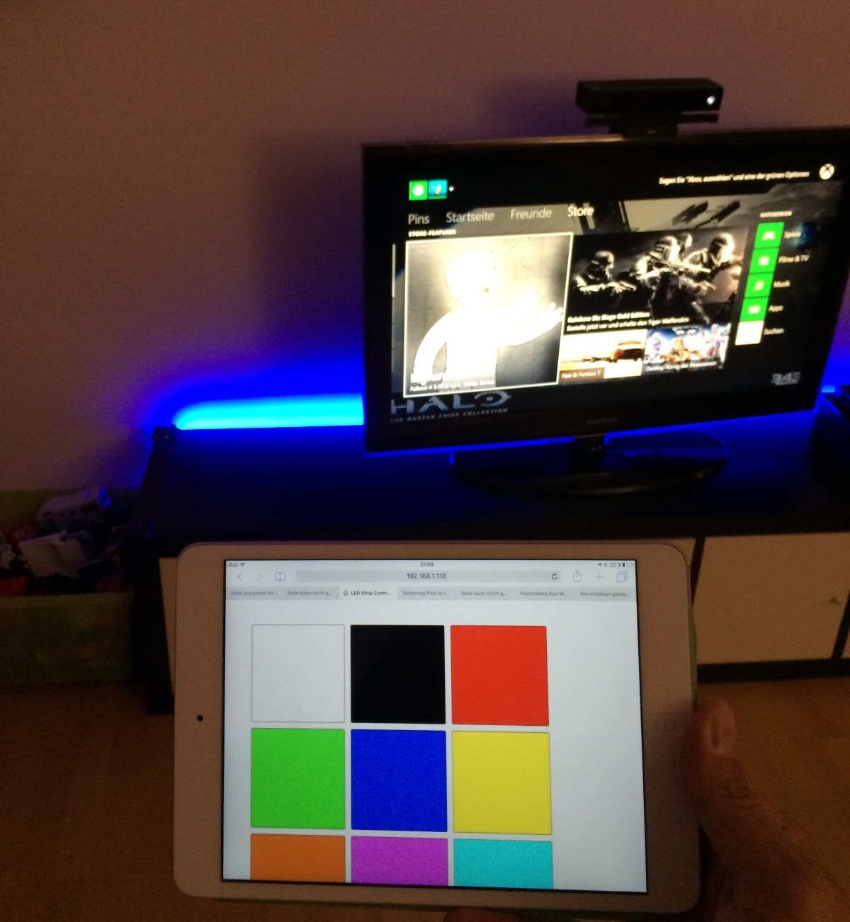
Here's the project in action. The color chooser web application is running on a RaspberryPi and is sending commands to the the Arduino which is then controlling the RGB LED strip.
What’s Next?
The web interface you see on the picture is really basic since I did not put much effort into it. The actual goal behind this project was having nice ambient lighting when watching TV. That means what I *really* want is for this LED strip to turn on and cycle colors automatically.
… but this will he part of a future blog post. Stay tuned!
